Current Calculator: How to Calculate Electric Current Using Ohm’s Law
Learning how to calculate current in physicsis one of the most fundamental skills in electricity and circuit analysis. Electric current tells you how much charge flows through a conductor every second, and it governs everything from the brightness of a light bulb to the performance of a computer processor. This current calculator uses Ohm's Law (I = V/R) to instantly solve for current, voltage, or resistance — plus it shows power dissipation and recommended wire gauges so you can go from formula to real-world application in seconds.
What Is Electric Current?
Electric current is the rate at which electric charge flows past a point in a circuit. It is measured in amperes (A), where 1 ampere equals 1 coulomb of charge passing through a cross-section of the conductor per second. Think of it like water flowing through a pipe — voltage is the water pressure, resistance is how narrow the pipe is, and current is how much water actually flows.
In metallic conductors, current is carried by electrons moving from the negative terminal to the positive terminal. However, conventional current direction is defined as flowing from positive to negative, which is the opposite of electron flow. This convention dates back to Benjamin Franklin and is still used in all circuit diagrams today.
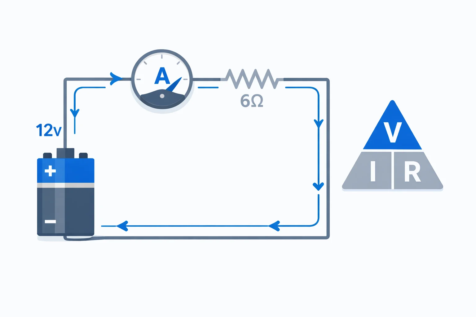
The Ohm's Law Formula: I = V / R
Ohm's Law is the cornerstone equation of circuit analysis. It states that the current through a conductor is directly proportional to the voltage across it and inversely proportional to its resistance:
- I = V / R — solve for current (amps)
- V = I × R — solve for voltage (volts)
- R = V / I — solve for resistance (ohms)
This relationship was discovered by Georg Simon Ohm in 1827 and applies to ohmic materials — conductors where resistance stays constant regardless of voltage. Most metals and standard resistors are ohmic at normal temperatures. Non-ohmic components like diodes and transistors do not follow this simple linear relationship.
Key Variables in Electric Current Calculations
Understanding each variable helps you predict how changing one affects the others:
- Voltage (V) — measured in volts (V). Doubling the voltage across a fixed resistor doubles the current. A standard AA battery supplies 1.5 V, a car battery 12 V, and a US wall outlet 120 V AC (170 V peak).
- Current (I) — measured in amperes (A). An LED draws about 20 mA (0.02 A), a phone charger about 2 A, and an electric oven up to 40 A.
- Resistance (R) — measured in ohms (Ω). A short copper wire might have 0.01 Ω, a standard resistor 100–10,000 Ω, and dry human skin roughly 100,000 Ω.
- Power (P) — measured in watts (W). Calculated as P = V × I. A 60 W light bulb on a 120 V circuit draws 0.5 A of current.
Worked Example: Finding Current in a Circuit
A 9 V battery is connected to a 150 Ω resistor. How much current flows through the circuit?
Step 1:Identify known values. V = 9 V and R = 150 Ω.
Step 2:Apply Ohm's Law. I = V / R = 9 / 150 = 0.06 A.
Step 3:Convert to milliamps if needed. 0.06 A = 60 mA.
Step 4:Calculate power dissipated by the resistor. P = V × I = 9 × 0.06 = 0.54 W.
This tells us the resistor needs to be rated for at least 0.54 watts. In practice, you'd choose a 1 W resistor for safety margin. You can verify this result instantly with the calculator above by entering V = 9 and R = 150.
Electrical Power and Current Relationship
Power and current are tightly linked through three equivalent formulas. Knowing any two of voltage, current, and resistance lets you calculate power:
- P = V × I — most direct form, used when you know both voltage and current
- P = I² × R — useful when current and resistance are known, shows that power scales with the square of current (doubling current quadruples power loss)
- P = V² / R — useful when voltage and resistance are known, common for calculating power in household circuits
The P = I²R relationship is especially important in electrical engineering because it explains why high-voltage transmission lines carry electricity across long distances. By increasing voltage and reducing current, power losses (I²R losses) in the wires drop dramatically. If you need to calculate power directly, our energy and power calculators provide additional tools for those conversions.
Current in Series vs Parallel Circuits
How current divides in a circuit depends on whether components are wired in series or parallel:
- Series circuit:The same current flows through every component. If three resistors of 2 Ω, 3 Ω, and 5 Ω are in series on a 10 V supply, the total resistance is 10 Ω and the current is 10 / 10 = 1 A through each resistor.
- Parallel circuit:The voltage is the same across each branch, but current splits. For two parallel resistors of 4 Ω and 12 Ω on a 12 V supply, the 4 Ω branch carries 3 A, the 12 Ω branch carries 1 A, and the total current is 4 A.
In parallel, the total resistance is always less than the smallest individual resistance. This is why adding more parallel branches increases total current draw from the source. Understanding these principles is essential for calculating total resistance in complex circuits.
Common Mistakes When Calculating Current
These pitfalls cause incorrect results and can lead to dangerous circuit designs:
- Mixing up units:Using kΩ instead of Ω in Ohm's Law gives answers off by a factor of 1,000. Always convert to base units (V, A, Ω) before plugging into formulas.
- Ignoring internal resistance:Real batteries have internal resistance (typically 0.1–1 Ω) that reduces the actual terminal voltage under load. A 9 V battery with 0.5 Ω internal resistance and a 4.5 Ω external load actually delivers only 8.1 V to the load.
- Applying Ohm's Law to non-ohmic devices:LEDs, diodes, and transistors do not have a constant resistance. Using V/R for these components gives wrong results. Use the device's characteristic curve or datasheet instead.
- Confusing conventional current with electron flow: Circuit diagrams show current from + to −, but electrons actually move from − to +. This doesn't affect Ohm's Law calculations, but matters when analyzing semiconductor devices.
Real-World Applications of Current Calculations
Knowing how to calculate current is critical in many practical scenarios:
- Sizing circuit breakers:A 20-amp kitchen circuit on 120 V can safely deliver 2,400 W. Running a 1,500 W microwave and a 1,000 W toaster on the same circuit draws 20.8 A — tripping the breaker.
- Choosing wire gauge:The NEC specifies minimum wire sizes based on current. A 30 A dryer circuit requires at least 10 AWG copper wire. Using undersized wire causes overheating and fire risk.
- Battery life estimation:A 3,000 mAh phone battery powering a device that draws 500 mA will last approximately 6 hours (3,000 / 500 = 6).
- Solar panel systems:A 300 W solar panel producing 30 V generates a maximum of 10 A. Wiring multiple panels in parallel increases current, requiring thicker cables and appropriately rated charge controllers.
For calculations involving force on current-carrying conductors in magnetic fields, see our Coulomb's Law calculator for electrostatic force between charges.
When to Use This Current Calculator
This current calculator is most useful when you need to:
- Quickly solve Ohm's Law for current, voltage, or resistance in homework or lab assignments
- Determine the current draw of a device to select the correct fuse or breaker rating
- Verify that a wire gauge is sufficient for the expected current in a circuit
- Calculate power dissipation in a resistor to choose the correct wattage rating
- Estimate battery drain and runtime for portable electronics or embedded projects
- Double-check hand calculations during physics exams or electrical engineering coursework