Resistance Calculator: How to Find Total Resistance in Series and Parallel Circuits
A resistance calculator saves you from the one formula most students mess up: parallel resistance. Series is straightforward addition. Parallel forces you through reciprocals, and a single arithmetic slip—forgetting to flip the final answer, say—gives you a number that's wildly wrong. This tool handles both configurations instantly, shows you the step-by-step math, and breaks down the voltage and current across every individual resistor in the circuit.
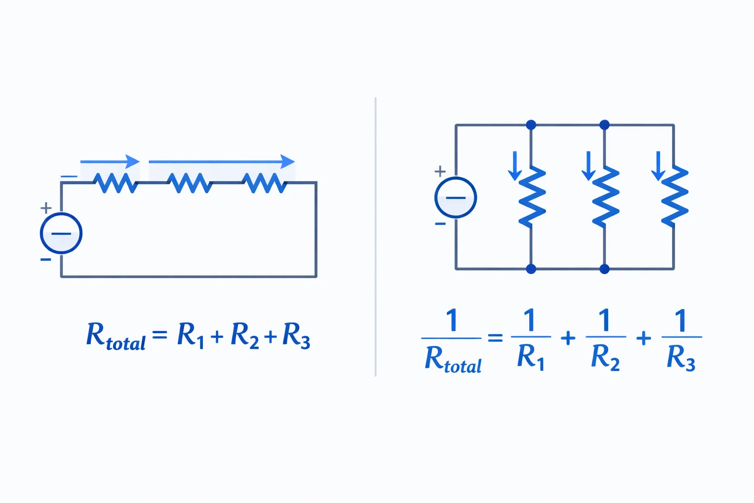
The Series Resistance Formula
When resistors sit end-to-end on a single path, you're looking at a series connection. The same current flows through every one of them, and resistances simply stack:
Rtotal = R1 + R2 + R3+ …
Put a 100 Ω and a 220 Ω resistor in series and the circuit sees 320 Ω. There's no trick to it. The total always exceeds the largest individual resistor because every component adds more opposition to current flow.
This matters practically: if you need a 470 Ω resistance but only have a 220 Ω and a 270 Ω in your parts bin, connecting them in series gets you 490 Ω—close enough for most hobby circuits where 5% tolerance resistors are standard anyway.
Parallel Resistance: The Reciprocal Method
Parallel resistors share the same two nodes, so each one sees the full supply voltage independently. The formula looks intimidating until you get the rhythm:
1/Rtotal = 1/R1 + 1/R2 + 1/R3+ …
The critical step everyone forgets: after adding the reciprocals, you must take the reciprocal of the sum. Skip that final flip and your answer is conductance in siemens, not resistance in ohms.
For exactly two resistors, there's a shortcut that avoids reciprocals entirely: Rtotal = (R1× R2) / (R1 + R2). Memorize this one. It shows up constantly on AP Physics exams and in lab work.
Worked Example: Three-Resistor Network
A student's breadboard has R1= 100 Ω, R2 = 200 Ω, and R3= 300 Ω. What does each configuration produce?
Series: Rtotal = 100 + 200 + 300 = 600 Ω. With a 12 V supply, the current is 12 / 600 = 0.02 A (20 mA). R1 drops 2 V, R2 drops 4 V, and R3drops 6 V—voltages that add up to exactly 12 V, confirming Kirchhoff's Voltage Law.
Parallel: 1/Rtotal = 1/100 + 1/200 + 1/300 = 0.01 + 0.005 + 0.00333 = 0.01833. So Rtotal= 1 / 0.01833 ≈ 54.5 Ω. Notice that's less than the smallest resistor (100 Ω)—parallel always pulls the total down. Use our Ohm's Law calculator to then find the total current drawn from the source: 12 V / 54.5 Ω ≈ 0.22 A.
Series vs. Parallel — When Total Goes Up or Down
Here's the intuition most textbooks skip. Series resistance goes upbecause you're forcing current through more obstacles on a single lane. Parallel resistance goes down because you're opening additional lanes for current to flow. Think of it like highway traffic: adding toll booths in a row slows everything down, but opening parallel lanes speeds things up.
A useful mental check: for N identical resistors of value R, series gives you N×R, and parallel gives you R/N. Ten 1 kΩ resistors in series = 10 kΩ. The same ten in parallel = 100 Ω. That's a 100× difference between the two configurations using identical parts.
Common Mistakes Students Make with Resistance
Mistake #1: Forgetting the final reciprocal. Students calculate 1/R1 + 1/R2 and report that sum as the answer. But that sum is conductance (1/Rtotal), not Rtotal itself. You must flip it at the end.
Mistake #2: Using the product-over-sum formula for three or more resistors. The shortcut Rtotal = (R1 × R2) / (R1 + R2) only works for exactly two resistors. For three or more, stick with the full reciprocal method.
Mistake #3: Mixing up series and parallel in combination circuits.Real circuits often have both. If you can't tell whether two resistors share the same current (series) or the same voltage (parallel), trace the current path from the battery terminal. If current must pass through both, they're in series. If current splits between them, they're in parallel.
Real-World Resistor Networks You Use Every Day
Voltage dividersare two resistors in series used to step down a voltage proportionally. Your phone's battery-level sensor uses one. Two equal 10 kΩ resistors across a 5 V rail produce 2.5 V at the midpoint—a level your microcontroller's ADC can safely read.
LED current limitinguses a single series resistor to prevent an LED from pulling too much current. For a standard red LED (2 V forward voltage, 20 mA target current) on a 5 V supply: R = (5 − 2) / 0.02 = 150 Ω. Grab a 220 Ω from the standard E24 series to run the LED a bit dimmer but safer. To find the exact current flowing through the LED, plug R and V into Ohm's Law.
Household wiringruns each outlet and fixture in parallel off the main breaker panel. That's why unplugging one lamp doesn't affect the others. The total resistance seen by the panel drops every time you plug in another device, which is why circuits trip when too many high-draw appliances share a breaker.
Resistivity vs. Resistance — They're Not the Same
Resistance (R, in ohms) depends on three things: the material, its length, and its cross-sectional area. Resistivity (ρ, in Ω·m) is the material's intrinsic property—it tells you how strongly a material opposes current regardless of its dimensions. The relationship is:
R = ρ × L / A
Copper's resistivity is 1.68 × 10⁻⁸ Ω·m. A 1-meter length of 14 AWG copper wire (cross-section 2.08 mm²) has a resistance of about 0.008 Ω—tiny, but it adds up over long runs. A 30-meter extension cord introduces roughly 0.5 Ω of total resistance, enough to cause a noticeable voltage drop under heavy load.
How Temperature Changes Resistance
Most metals behave predictably: heat them up, resistance goes up. Copper's resistance increases about 0.4% per degree Celsius. An incandescent light bulb's tungsten filament is roughly 10× more resistive when glowing white-hot (2500°C) than at room temperature. That initial low resistance explains the surge of current when you flip the switch—and why bulbs tend to burn out the instant you turn them on.
Semiconductors go the other direction. Silicon's resistance drops as it heats up, which is why overheating can cause thermal runaway in transistors: more heat means less resistance, which allows more current, which generates even more heat. This is also the principle behind thermistors used in thermodynamics applications for temperature sensing.
When to Use This Resistance Calculator
Pull up this tool whenever you're designing a circuit with multiple resistors and need the equivalent value fast. It's especially useful for:
- Homework and AP Physics prep— check your manual reciprocal calculations against the step-by-step breakdown
- Breadboard prototyping— figure out which standard resistor values to combine when you don't have the exact value you need
- Circuit debugging— verify expected resistance matches your multimeter reading
- Power budgeting— use the per-resistor power column to ensure no component exceeds its wattage rating (most through-hole resistors max out at 250 mW)
- RC and filter design— pair your resistance value with our capacitance calculator to find equivalent capacitance for series/parallel capacitor networks and compute RC time constants