Understanding Capacitance: Parallel Plates, Series & Parallel Combinations, and Stored Energy
A capacitance calculator saves you from the tedious unit conversions and reciprocal math that make capacitor problems feel harder than they actually are. Whether you're sizing a parallel plate capacitor for a lab report or figuring out the equivalent capacitance of a filter network on a PCB, the underlying physics is straightforward — but the arithmetic gets messy fast. This guide walks through every formula you'll need, with worked examples that go beyond the textbook basics.
The Parallel Plate Capacitance Formula
Every intro physics course starts with the parallel plate capacitor because it's the simplest geometry to analyze. Two flat conducting plates, area A, separated by distance d, filled with a dielectric of constant εr:
C = ε0 × εr× A / d
Here ε0 = 8.854 × 10⁻¹²F/m is the permittivity of free space. Two things jump out from this formula. First, capacitance scales linearly with plate area — double the area, double the capacitance. Second, capacitance is inversely proportional to separation. Halve the gap and you double C. This is why real capacitors use extremely thin dielectric layers, sometimes just a few micrometers thick.
A quick sanity check: two 10 cm × 10 cm plates (A = 0.01 m²) separated by 1 mm of air give C = 8.854 × 10−12 × 1 × 0.01 / 0.001 = 88.5 pF. That's tiny. It takes clever engineering — thin gaps, high-εr dielectrics, rolled or stacked geometries — to get the microfarad-range values you see in real circuits. If you're curious about the electric field strength between those plates, it follows directly from E = V/d.
Dielectrics Change Everything
Slide a slab of glass (εr ≈ 7.5) between those same plates and the capacitance jumps from 88.5 pF to 664 pF — nearly 7.5× more. Ceramic materials push εrinto the thousands. That's how a tiny surface-mount ceramic capacitor the size of a grain of rice stores 100 µF.
But there's a trade-off most textbooks gloss over. High-εr ceramics (Class II and III) lose capacitance as voltage increases, as temperature drifts, and as they age. A "100 µF" ceramic cap at its rated voltage might actually measure 40 µF under bias. Class I ceramics (like C0G/NP0) have low εrbut exceptional stability — making them the go-to for precision timing and filter circuits. Understanding this distinction is what separates textbook knowledge from practical circuit design.
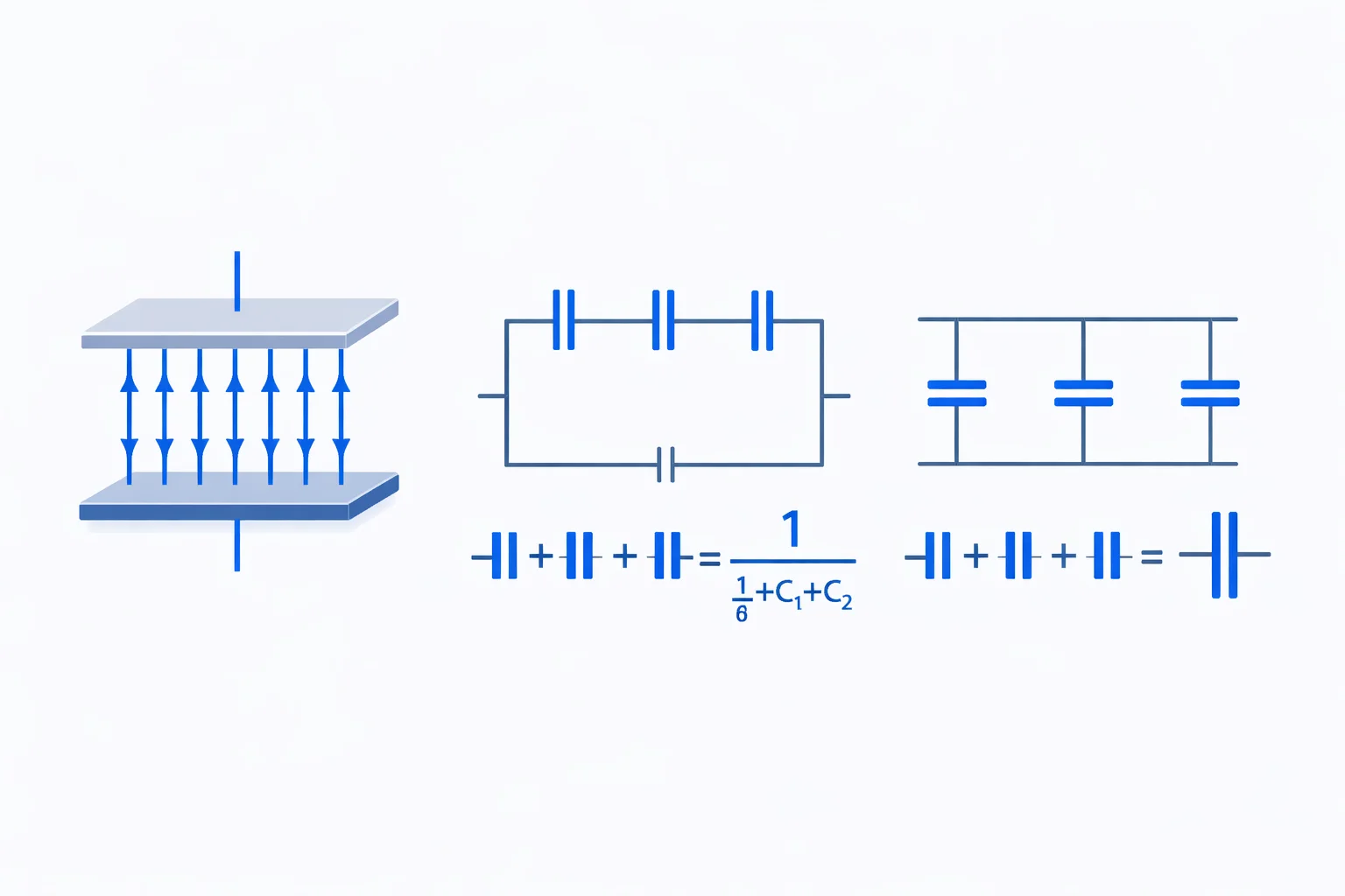
Series vs. Parallel: Capacitors Behave Backwards
If you already know how resistors combine in series and parallel, prepare to flip your intuition. Capacitors do the exact opposite:
- Parallel: Ctotal = C1 + C2 + C3 — capacitances add directly. More plate area in parallel means more charge storage.
- Series: 1/Ctotal = 1/C1 + 1/C2 + 1/C3 — the reciprocal formula. Total capacitance is less than the smallest individual capacitor.
Why would anyone put capacitors in series if it reduces total capacitance? Voltage rating. Each capacitor in series only sees a fraction of the total voltage. Three 16 V capacitors in series can handle 48 V across the combination. This is exactly how engineers design high-voltage power supplies — they sacrifice capacitance for voltage headroom.
Worked Example: A Mixed Capacitor Circuit
Here's a problem that actually shows up on AP Physics exams and in intro E&M courses. You have three capacitors: C1 = 20 µF and C2 = 30 µF in parallel with each other, and that parallel combination is in series with C3 = 10 µF. The source voltage is 24 V. Find the total capacitance, the charge on C3, and the voltage across the parallel pair.
Step 1: Combine the parallel pair. C12= 20 + 30 = 50 µF.
Step 2: Now C12 (50 µF) is in series with C3 (10 µF). Use the reciprocal formula: 1/Ctotal = 1/50 + 1/10 = 0.02 + 0.1 = 0.12. So Ctotal= 1/0.12 = 8.333 µF.
Step 3: Total charge Q = Ctotal × V = 8.333 × 10−6 × 24 = 200 µC. In a series connection, every capacitor carries the same charge, so Q3 = 200 µC and Q12= 200 µC.
Step 4: Voltage across C3 = Q/C3 = 200/10 = 20 V. Voltage across the parallel pair = Q/C12 = 200/50 = 4 V. Check: 20 + 4 = 24 V. It adds up.
Notice something? The 10 µF capacitor — the smallest one — hogs 20 out of 24 volts. Smaller capacitors in series always take the larger voltage share. That's a detail worth remembering for exams.
Energy Stored in a Capacitor
A charged capacitor is an energy reservoir. The stored energy follows three equivalent forms:
E = ½CV² = ½QV = Q²/(2C)
The V² dependence is the key insight. Double the voltage and you quadruple the energy. That's why a 400 V capacitor in a camera flash (even a small one) packs a painful punch, while a 5 V supercapacitor of much larger capacitance stores relatively little energy. This stored energy comes from the work done against the electrostatic force between charges as they accumulate on the plates.
Quick calculation: a 470 µF electrolytic capacitor charged to 25 V stores ½ × 470 × 10−6× 625 = 0.147 J. Not much. But a 1 mF capacitor at 450 V (common in motor start circuits) stores ½ × 0.001 × 202,500 = 101.25 J — enough to be genuinely dangerous. Always discharge high-voltage capacitors before working on equipment.
Where Capacitors Actually Matter
Capacitors show up everywhere, but here are the applications where getting the capacitance right actually matters:
- Power supply filtering: A rectified AC signal needs bulk capacitance (often 1,000–10,000 µF) to smooth ripple. Too little capacitance and your voltage sags between cycles. Too much and inrush current destroys your bridge rectifier. Use our Ohm's Law calculator to check current demands alongside your capacitor sizing.
- RC timing circuits: The RC time constant τ = R × C sets how fast a capacitor charges to 63.2% of the supply voltage. A 10 kΩ resistor with a 100 µF capacitor gives τ = 1 second. Change either component and the timing shifts proportionally.
- Signal coupling and decoupling: Coupling capacitors block DC and pass AC between amplifier stages. Decoupling caps (typically 0.1 µF ceramic right at the IC power pin) absorb high-frequency noise before it corrupts digital signals.
- Touchscreens: Your phone's touchscreen is a grid of tiny capacitors. When your finger (a conductor) gets close, it changes the local capacitance. The controller detects that shift — that's capacitive sensing.
Mistakes That Cost Exam Points
After grading hundreds of physics exams, these are the errors that come up over and over:
- Confusing series capacitors with series resistors. Resistors in series add directly. Capacitors in series use the reciprocal formula. If you mix them up, your answer will be off by a lot, not a little.
- Forgetting to convert units. The formula C = ε0εrA/d requires meters and farads. Students who plug in centimeters for plate area or millimeters for separation get answers that are off by factors of 102 to 106.
- Ignoring which quantities stay constant. When a dielectric is inserted into an isolated (disconnected) capacitor, charge Q stays constant but voltage changes. When inserted into a capacitor that's still connected to a battery, voltage stays constant but charge changes. This distinction is the single most-tested capacitor concept on AP Physics C.
- Wrong energy formula. E = ½CV² is correct. Students sometimes write E = CV² or E = ½CV, both of which are wrong. Remember: integrating V dQ from 0 to the final charge gives the ½ factor.
Capacitor Types at a Glance
Different capacitor technologies serve different roles. Here's a quick reference to help you pick the right type when using the current calculator to check circuit behavior:
| Type | Range | Max Voltage | Best For |
|---|---|---|---|
| Ceramic (MLCC) | 1 pF – 100 µF | 6.3 – 100 V | Decoupling, HF filtering |
| Aluminum electrolytic | 0.1 – 100,000 µF | 6.3 – 500 V | Power supply filtering |
| Film (polyester/polypropylene) | 100 pF – 10 µF | 50 – 2000 V | Audio, timing, AC filtering |
| Tantalum | 0.1 – 1,000 µF | 2 – 50 V | Compact, low-ESR filtering |
| Supercapacitor (EDLC) | 0.1 – 3,000 F | 2.5 – 5.5 V | Energy storage, backup power |
Notice the supercapacitor line — those are measured in farads, not microfarads. A single supercap can store 3,000 F at 2.7 V, which is about 11 kJ of energy. Enough to briefly power a small motor or keep a microcontroller alive for hours during a power outage.