RC Circuits Explained: Time Constants, Exponential Curves, and Why 5τ Isn't Really "Fully Charged"
An RC circuit calculator helps you predict exactly how a capacitor behaves over time — but the math behind it trips up more students than almost any other circuit topic. The confusion usually isn't about the formula itself. It's about what the exponential curve meansphysically, and why the capacitor never technically finishes charging. If you've stared at a voltage-vs-time graph and wondered where the "done" point is, you're asking the right question.
τ = RC: The One Equation That Governs It All
The time constant τ (tau) is simply resistance times capacitance: τ = R × C. That's it. Ohms times farads gives you seconds. A 10 kΩ resistor paired with a 47 μF capacitor produces τ = 10,000 × 0.000047 = 0.47 seconds. This single number controls the entire charging and discharging behavior of the circuit.
What makes τ useful is its physical meaning. After exactly one time constant, a charging capacitor reaches 63.2% of the supply voltage — not 50%, not some round number. That 63.2% comes from 1 − e⁻¹ ≈ 0.632, a consequence of the exponential differential equation that governs current flow through the resistor. The bigger R is, the harder it is for current to flow, so charging takes longer. The bigger C is, the more charge the capacitor needs to store, so again — longer. Both factors multiply linearly into τ.
You can use our resistance calculatorif you're working with series or parallel resistor combinations and need the equivalent R value before calculating the time constant.
Charging vs. Discharging — Same τ, Mirror Curves
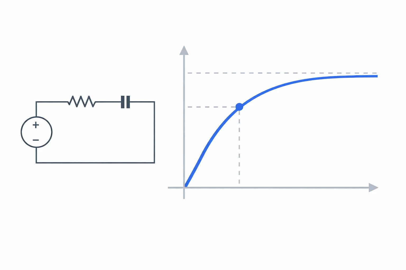
During charging, the capacitor voltage follows V(t) = V₀ × (1 − e^(−t/τ)). It starts at zero and climbs toward the supply voltage V₀, slowing down as it approaches. Current starts at its maximum value I₀ = V₀/R and decays exponentially.
During discharging, everything flips. Voltage drops as V(t) = V₀ × e^(−t/τ), starting at V₀ and decaying toward zero. Current also decays, but flows in the opposite direction. Here's the key insight: the time constant τ doesn't change between charging and discharging. It depends only on R and C, not on the direction of current flow. Swap the sign of the exponential and you get the mirror curve.
One subtle point that textbooks sometimes gloss over: during discharging, the current is negative (flowing opposite to the charging direction). The magnitude decays the same way, but the sign matters if you're applying Kirchhoff's voltage law around the loop.
Worked Example: Camera Flash Circuit
A disposable camera flash uses a 330 μF capacitor charged through a 15 kΩ resistor from a 300 V supply (boosted from a 1.5 V battery by a voltage multiplier). Let's trace the numbers:
Step 1 — Find τ: τ = 15,000 Ω × 330 × 10⁻⁶ F = 4.95 seconds.
Step 2 — Voltage after 5 seconds (roughly 1τ): V(5) = 300 × (1 − e^(−5/4.95)) = 300 × (1 − 0.364) = 300 × 0.636 = 190.8 V. Not enough for a full flash yet.
Step 3 — Time to 95% charge (3τ):3 × 4.95 = 14.85 seconds. At this point, V = 300 × 0.95 = 285 V. That's why disposable cameras make you wait ~15 seconds between flash shots — the capacitor genuinely needs three time constants to reach usable voltage.
Step 4 — Energy stored at full charge: E = ½CV² = 0.5 × 330 × 10⁻⁶ × 300² = 14.85 joules. Enough to produce a bright visible flash lasting a few milliseconds.
If you need to find the capacitance value for a specific circuit, our capacitance calculator handles parallel plate geometries and series/parallel combinations.
The 5τ Rule and Why It's an Approximation
Every electronics textbook states that a capacitor is "fully charged" after 5τ. The reality is messier. At 5τ, the capacitor is at 99.33% of the supply voltage — not 100%. The exponential function e^(−5) = 0.0067, so 0.67% of the voltage is still missing.
For most circuits, 99.3% is indistinguishable from "done." But in precision analog circuits, high-resolution ADCs, or sample-and-hold amplifiers, that last 0.67% matters. A 16-bit ADC has a resolution of 1/65,536 ≈ 0.0015%, meaning you'd actually need about 11τ to settle within one least significant bit. The 5τ rule is a rule of thumb, not a law of physics.
Here's a quick reference for how many time constants you need at different accuracy levels:
- 1τ: 63.2% — barely past halfway
- 2τ: 86.5% — getting there
- 3τ: 95.0% — good enough for many applications
- 4τ: 98.2% — solid for most digital circuits
- 5τ: 99.3% — the textbook "fully charged"
- 7τ: 99.91% — precision analog territory
- 10τ: 99.995% — lab-grade settling
Half-Life in RC Circuits
The half-life of an RC circuit — the time for a discharging capacitor to lose half its voltage — is t½ = τ × ln(2) ≈ 0.693τ. This is mathematically identical to radioactive half-life, and that's not a coincidence. Both processes follow the same differential equation: the rate of change is proportional to the current value. Whether it's unstable atoms or electrons flowing through a resistor, exponential decay is exponential decay.
Half-life is sometimes more intuitive than τ for quick mental math. If τ = 10 ms, the half-life is about 6.93 ms. After two half-lives (13.86 ms), the voltage drops to 25%. After three half-lives (20.79 ms), it's at 12.5%. Each half-life cuts the remaining voltage in half — easy to track in your head without a calculator.
Where RC Circuits Actually Show Up
RC circuits aren't just textbook exercises. They're embedded in nearly every electronic system you touch:
- Audio tone controls: The bass and treble knobs on an amplifier are RC low-pass and high-pass filters. A low-pass filter with R = 10 kΩ and C = 1.6 nF has a cutoff frequency of about 10 kHz — it passes bass frequencies and attenuates treble. Turning the knob effectively changes R, shifting the cutoff.
- Touchscreen debouncing: When you tap a capacitive touchscreen, the controller uses an RC time constant to filter out electrical noise and register a clean touch event. Too short a τ and you get phantom touches; too long and the screen feels laggy.
- Power supply smoothing: The ripple voltage after a rectifier gets smoothed by large electrolytic capacitors. A 1000 μF cap with a 100 Ω effective load gives τ = 0.1 s, enough to maintain relatively steady DC between 60 Hz rectification cycles (16.7 ms period).
- Defibrillators: Medical defibrillators charge a capacitor bank to 200-360 joules through a carefully controlled RC circuit, then dump that energy through the patient's chest in about 4-12 ms. The charging time constant determines how quickly the unit is ready.
Mistakes That Cost Exam Points
After grading hundreds of AP Physics C exams, certain mistakes come up over and over. Here's what to watch for:
Using the wrong equation for the mode. The charging equation V(t) = V₀(1 − e^(−t/τ)) starts at zero and rises. The discharging equation V(t) = V₀ × e^(−t/τ) starts at V₀ and falls. Students mix these up under time pressure. Quick check: plug in t = 0. If the capacitor starts uncharged, V(0) should be 0 — only the charging equation gives that.
Forgetting to convert units. If R is in kΩ and C is in μF, you can't just multiply the numbers. Either convert both to base units (Ω and F) or know the shortcut: kΩ × μF = milliseconds. So 4.7 kΩ × 22 μF = 103.4 ms = 0.1034 s. Getting familiar with Ohm's law relationships helps you catch unit errors faster.
Assuming the capacitor is fully charged after 5τ.If a problem asks "how long until the capacitor is fully charged?" the technically correct answer is "never" — it's an asymptote. But if they ask "approximately fully charged," then 5τ is the expected answer. Read the question carefully.
Confusing capacitor voltage with resistor voltage.During charging, V_capacitor + V_resistor = V₀ at all times (Kirchhoff's voltage law). When the capacitor is at 63.2% of V₀, the resistor has the remaining 36.8%. These two voltages don't behave the same way — the capacitor voltage increases while the resistor voltage decreases.
Common RC Combinations Reference
Here are time constants for some frequently encountered component pairings. These are useful for quick estimation when you don't have a calculator handy:
| Resistance | Capacitance | τ (Time Constant) | Typical Application |
|---|---|---|---|
| 1 kΩ | 1 μF | 1 ms | Audio filter crossover |
| 10 kΩ | 100 nF | 1 ms | Signal coupling/decoupling |
| 100 kΩ | 10 μF | 1 s | LED fade effect |
| 1 MΩ | 1 μF | 1 s | Sensor input filtering |
| 10 kΩ | 470 μF | 4.7 s | Power-on delay circuit |
| 47 kΩ | 100 μF | 4.7 s | Slow ramp-up control |
| 1 kΩ | 100 pF | 100 ns | High-speed digital filtering |
| 50 Ω | 10 pF | 500 ps | RF impedance matching |
A handy unit shortcut to memorize: kΩ × μF = ms, and MΩ × μF = s. This lets you estimate time constants mentally without converting to base SI units every time.