A Leaking Water Main, a Missing Variable, and the Equation That Finds It
The Leaked Water Main Problem
A utility crew finds a cracked 150 mm water main leaking into a trench. The pipe is still pressurized, and the supervisor needs to know: how many liters per minute is this system supposed to deliver before we can shut it down and reroute? A flow rate calculatoranswers that in under five seconds. Measure the pipe's internal diameter, estimate the fluid velocity from the system's design spec (typically 1.5 m/s for a municipal main), and compute Q = Av. For a 150 mm pipe at 1.5 m/s, that's Q = 0.0177 m² × 1.5 m/s = 0.0265 m³/s — roughly 1,590 liters per minute. That single number tells the crew whether a temporary bypass line can handle the rerouted demand or whether they need to throttle pressure first.
That scenario isn't hypothetical. Municipal engineers run this calculation daily. But flow rate shows up far beyond city infrastructure — it governs IV drip rates in hospitals (typically 0.5–4 mL/min), fuel injection in engines (40–80 mL/s for a 2.0 L gasoline engine), and coolant circulation in data centers. The math is always the same equation. What changes is which variable you know and which you need to find.
Q = Av: What Each Variable Actually Controls
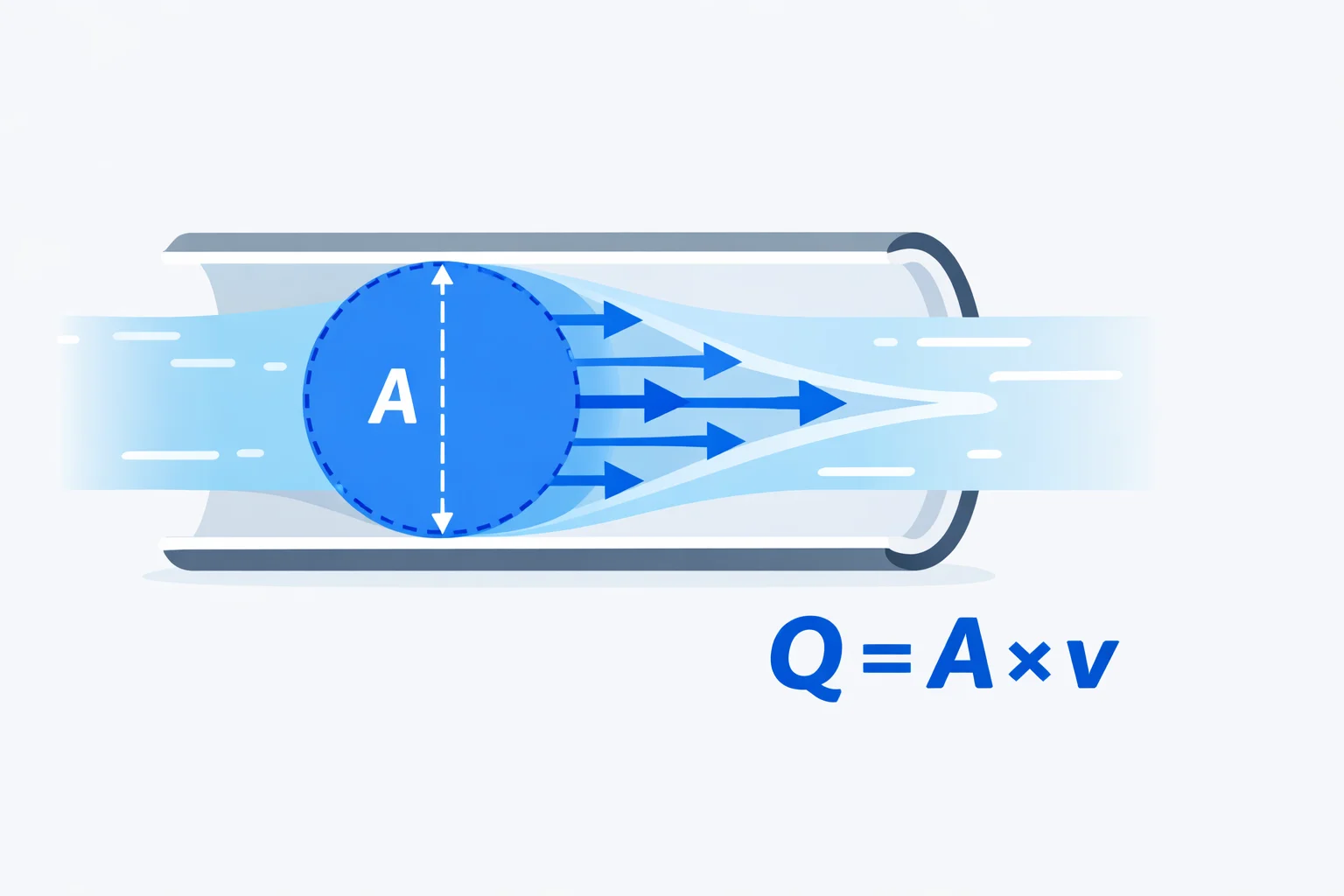
Volumetric flow rate Q equals cross-sectional area A multiplied by average fluid velocity v. The formula looks trivially simple, and that's deceptive — the hard part is getting each input right.
Area (A)depends on the internal diameter, not the nominal pipe size. A "1-inch" Schedule 40 steel pipe has an internal diameter of 26.6 mm, giving an area of 5.56 cm². A "1-inch" PVC pipe has an ID of 27.8 mm, or 6.07 cm². That 9% area difference means 9% more flow at the same velocity. Always use the actual ID, not the label on the box.
Velocity (v)is the average velocity across the full cross-section. In laminar flow (Reynolds number below 2,300), the velocity profile is parabolic: zero at the wall, maximum at the center, with an average that's exactly half the peak. In turbulent flow (Re above 4,000), the profile flattens and the average is roughly 82% of the centerline velocity. If you measured velocity with a pitot tube at the pipe center, you need to apply a correction factor before plugging it into Q = Av.
Qhas units of volume per time. In SI, that's m³/s, but engineers rarely use that — the numbers are tiny for most practical pipes. Instead you'll see liters per second (L/s), liters per minute (L/min), or US gallons per minute (GPM). 1 m³/s = 1,000 L/s = 15,850 GPM. Mixing up L/s and L/min is a factor-of-60 error that's more common than anyone admits.
Volumetric vs. Mass Flow Rate: When Each One Matters
Volumetric flow rate (Q, in m³/s) tells you how much space the fluid occupies per second. Mass flow rate (\u1E41, in kg/s) tells you how much matter passes per second. For incompressible liquids like water, you can freely convert between them: \u1E41 = ρ × Q. At 998 kg/m³, a volumetric flow of 10 L/s equals 9.98 kg/s. Simple.
For gases, it's not that clean. Air at sea level has ρ = 1.225 kg/m³, but at 3,000 m altitude, density drops to about 0.91 kg/m³. The same volumetric flow of 1 m³/s delivers 26% less mass at altitude. That's why jet engines lose thrust at high altitude, why combustion engineers spec mass flow rate instead of volumetric, and why HVAC systems designed for Denver need larger ducts than systems designed for Miami.
| Quantity | Symbol | Units | Use When |
|---|---|---|---|
| Volumetric flow rate | Q | m³/s, L/s, GPM | Pipe sizing, pump selection, water systems |
| Mass flow rate | \u1E41 | kg/s, g/min | Combustion, chemical reactions, gas systems |
Worked Example: Sizing an Irrigation System
You're designing a drip irrigation layout for a 500 m² vegetable garden. Each emitter delivers 2 L/h, and you need 200 emitters. What pipe diameter do you need for the main supply line?
Step 1: Total flow rate.200 emitters × 2 L/h = 400 L/h = 6.67 L/min = 0.111 L/s = 1.11 × 10&sup4; m³/s.
Step 2: Choose a velocity.For drip irrigation supply lines, recommended velocity is 0.5–1.5 m/s. Go with 1.0 m/s to keep friction losses low.
Step 3: Solve for area.A = Q / v = 1.11 × 10&sup4; m³/s ÷ 1.0 m/s = 1.11 × 10&sup4; m².
Step 4: Find diameter.A = πd²/4, so d = √(4A/π) = √(4 × 1.11 × 10&sup4; / 3.14159) = 0.0119 m = 11.9 mm. A standard 13 mm (half-inch) poly pipe works. If you went with 1.5 m/s velocity, you'd need only 9.7 mm — technically possible with 10 mm tubing, but the higher velocity means higher friction losses and lower pressure at the far end of the line.
The Continuity Equation and Pipe Constrictions
When an incompressible fluid flows through a pipe that changes diameter, Q stays constant. This is the continuity equation: A₁v₁ = A₂v₂. If a 100 mm pipe necks down to 50 mm, the area drops by a factor of 4 (area scales with d²), so velocity quadruples. Water flowing at 1.5 m/s in the wide section hits 6.0 m/s in the narrow section. That's where things get interesting for Bernoulli's equation: the velocity increase means a pressure drop, which is exactly how Venturi meters and carburetors work.
The continuity equation breaks down in two situations. First, if the fluid is compressible (like air at high Mach numbers), density changes between the two sections and you need ρ₁A₁v₁ = ρ₂A₂v₂ instead. Second, if there are branches — a tee fitting splitting flow into two paths — you need Q_in = Q_out1 + Q_out2. The calculator's continuity mode handles the straight-pipe case; for branching networks, apply the principle at each junction separately.
Recommended Pipe Velocities by Application
Picking the right velocity is as important as getting the area right. Too slow and pipes are oversized (wasted money). Too fast and you get erosion, noise, water hammer, and excessive friction losses. These values come from engineering handbooks and industry standards:
| Application | Fluid | Velocity (m/s) | Why This Range |
|---|---|---|---|
| Domestic water supply | Water | 0.5 – 2.0 | Above 2.0 causes noise in walls |
| Fire sprinkler mains | Water | 3.0 – 5.0 | Higher velocity acceptable for emergency flow |
| HVAC ductwork | Air | 5.0 – 12.0 | Above 12 m/s generates audible duct noise |
| Industrial compressed air | Air | 6.0 – 10.0 | Balances pressure drop vs. pipe cost |
| Oil pipelines | Crude oil | 1.0 – 3.0 | Higher viscosity requires slower flow |
| Chemical process piping | Various | 1.0 – 2.5 | Erosion and corrosion limits for aggressive fluids |
| Hydraulic power lines | Hydraulic oil | 3.0 – 6.0 | Pressure lines tolerate higher velocity than return |
Three Mistakes That Wreck Flow Rate Calculations
Mistake 1: Using nominal diameter instead of internal diameter. A "2-inch" copper pipe (Type L) has an internal diameter of 51.0 mm, not 50.8 mm (2 inches). A "2-inch" Schedule 80 steel pipe has an ID of 49.2 mm. That's a 7% area difference between two pipes both labeled "2 inch." For a pressure drop calculation, that 7% area error compounds into a 14% flow rate error at constant pressure.
Mistake 2: Confusing average velocity with centerline velocity.A pitot tube at the pipe center reads the maximum velocity, not the average. In turbulent flow (most practical pipe systems), average velocity is about 82% of centerline velocity. If you measured 3.0 m/s at the center and used that directly, you'd overestimate Q by 22%. In laminar flow, the error is even worse — average velocity is exactly 50% of centerline.
Mistake 3: Ignoring units in unit conversions.1 L/s = 60 L/min = 15.85 GPM = 0.001 m³/s. Getting these wrong by a factor of 60 or 1,000 is embarrassingly common in student work and occasionally in engineering reports. The fix: always carry units through every step and check that both sides of the equation have the same dimensions.
When Q = Av Isn't Enough: The Reynolds Number Connection
Q = Av gives you the flow rate, but it tells you nothing about the flow's character. Is the flow smooth and orderly (laminar) or chaotic and swirling (turbulent)? The Reynolds number Re = ρvd/μ answers that. For pipe flow, Re below 2,300 is laminar, above 4,000 is turbulent, and the range between is transitional.
Why does this matter for flow rate? Because the velocity profile — and therefore the relationship between average velocity and measurable velocity — depends entirely on the flow regime. In laminar flow, friction losses scale linearly with velocity (Hagen-Poiseuille equation). In turbulent flow, losses scale with v¹·⁸⁄₁ approximately, which means doubling the velocity roughly quadruples the friction loss. If you're designing a pipe system, calculating Q is step one. Checking Reynolds number to confirm your friction factor is step two. The buoyancy calculatoruses the same fluid density ρ that appears in Reynolds number — the fluid mechanics toolkit is deeply interconnected.